Today’s journey will be about something very interesting to me, hardware hacking.
We are going to dive into a TV receiver PCB to get a root shell with its processing unit.
Important Notes:
-First off, it’s important to make sure that you have some basic electronics and serial communication knowledge, this is going to be the base of the article.
– We are going to use two basic tools in order to reverse engineer the RS-232 serial port, a Multimeter and a USB to UART adapter for voltage level and protocol conversions.
– Personally, I’m going to work on a Linux machine (Arch 64-bit), and minicom script. You are definitely free to get your favorite toolset, as long as it gets the job done.
– What we are going to do in here could be applied to any piece of hardware, as well as any type of protocols.
– Be extremely cautious when applying the steps mentioned in here and/or any type of hardware tinkering. Misapplying/misunderstanding any of the steps can very much fry your hardware and cause physical harm.
———————————————————————————–
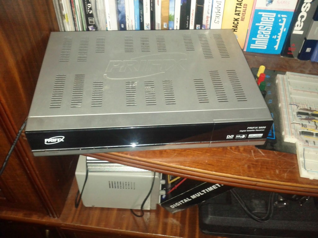
Our target hardware is the Prifix 9500 Digital Satellite TV Receiver, here is a photo of it before taking the cover apart:
After taking the cover apart and disconnecting the power board, we end up with the main board of the receiver.
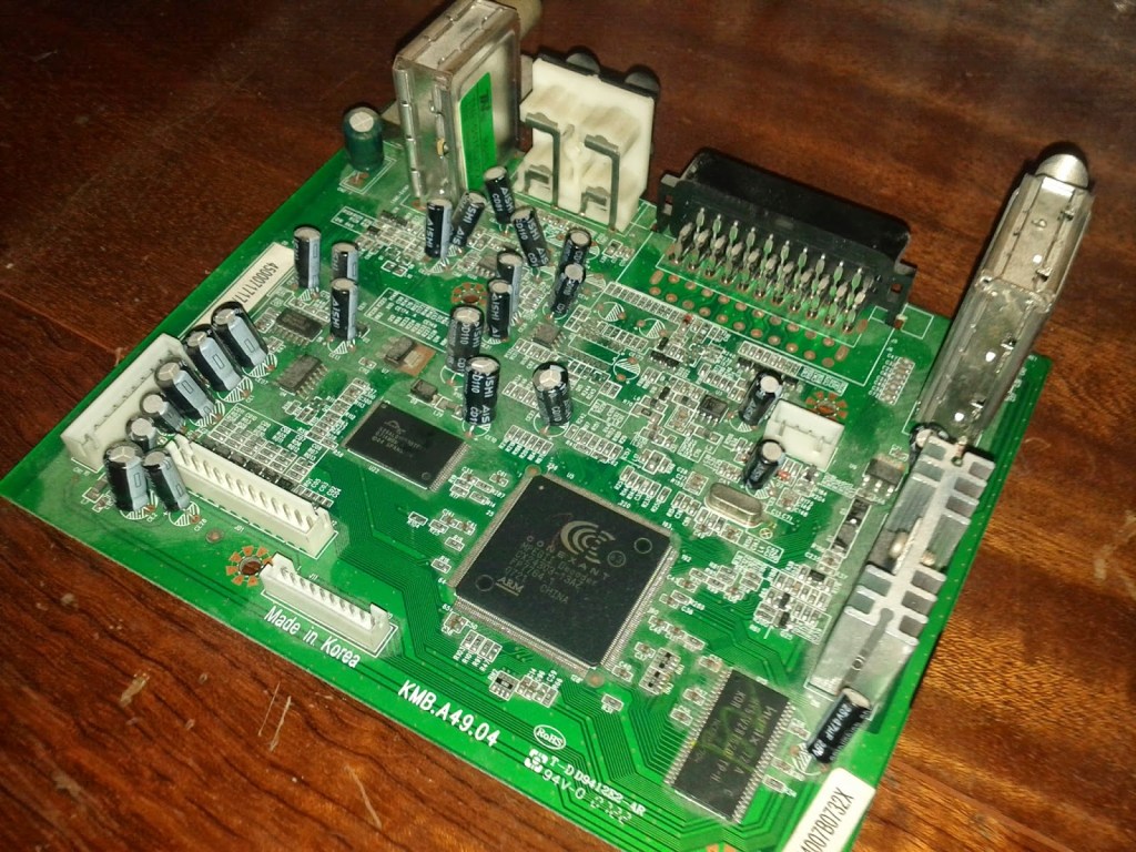
From the photo, we can recognize some of the on-board chips:
– Hyundai HY57V28162XX DRAM: A synchronous CMOS Dynamic RAM, with a capacity of 4 blocks, each 2M, with 16-bit bandwidth.
– Conexant CX24303 ARM CPU: A 32-bit RISC processing unit, also includes a tv tuner, MPEG decoder, and many other processing features.
– Spanion S29AL016D70TF: A 16-Megabit CMOS ROM for the bootstrap and firmware storage.
We can also notice some JTAG’s, in the middle of the top part of the board.
So far so good, we now have a rough idea of the main chips of the board. What we are interested in right now is some sort of serial communication headers/pins. Usually serial communication ports constitute of a simple header with at least 2 pins, a Tx and Rx for the transmission and reception of the data, respectively.
After some fuzzing, 4 pins were located at the back of the board, most probably a serial header. Only 2 4-pin headers were found in total, one connected to some decoupling capacitors, and another connected to nothing. (could be a disconnected JTAG?)
Now, our next task would be to validate whether these 4 pins are indeed a serial header, and playing a bit with the voltage/current in order to identify which pin does what.
My presumption is the 4 pins are a ground pad, a Vcc source, Tx, and Rx.
Let’s start with the simplest one, the ground pin. In order to know which of the 4 pins is ground, we can se the continuity test. Placing one probe of the Multimeter on the pin, and the other probe on any conducting metal surface on the board, personally, I love the co-axial LNB port, so I’ll use that.
My multimeter buzzed at pin number 4, therefore this is the ground pin.
Now, let’s move to another simple identifiable pin, the Vcc source. Simply see which pin outputs a stable CMOS HIGH voltage level, and that’s the Vcc. Connect and switch the power board on, set your Multimeter to Voltage reading mode, and place one probe on the GND pin (or any conducting metal in the board), and the other probe on each of the remaining 3 (or more) pins, if your probe is on the Vcc, you should a stable voltage value (most probably 3.3 or 5 volts).
Make sure to keep the probes connected for a while (~5 seconds or so), because the Transmitter pin outputs some voltage bursts as well.
Now we have two remaining pins, the Tx and Rx. It’s hard to identify the Rx because of the fact that this pin only receives data, so if we place our probe on it, it won’t provide us with any readings. However, we can identify the Tx, and by elimination, conclude that the remaining pin will be the Rx.
To locate the Tx pin, we will set our Multimeter device on the voltage reading mode, and place the probe on one of the remaining pins, if it’s the Tx, we should see a non-stable signal, i.e. an oscillating voltage. A packet analyzer could be used to easily identify such a pin.
Now that we’ve identified the serial pins, we are ready to connect our computer to the board through the protocol adapter.
So why exactly are we using an adapter in here?
The serial header uses RS-232 protocol, which uses the standard digital logical values which usually have values between -25 volts to +25 volts. While our computer’s USB interface uses the differential protocol, it uses the logical values 0V~5V. So we need to make sure that the RS-232 logical levels are converted to the USB levels, as well as reversing the bits (so that 0 becomes 1 and vice-versa, they are reversed in the RS-232 protocol).
Just before connecting our computer to the board, we have to identify the communication parameters of the RS-232 protocol.
Most devices use 8N1, and 9600/115200 baud rates for asynchronous serial communications, which means 8 data bits, 1 stop bit, 1 start bit, and no parity checks, the communication is set to the speed of 9600 or 115200 symbols/second. I used a bruteforce approach in here, playing with the parameters until I could see readable ASCII on my terminal.
The parameters that the board was tuned to are 8N1, with 115200 baud rate, so I set up the minicom settings to open a listener on a dev file /dev/ttyUSB0 with the serial parameters. Turned on the power board of the PCB, and finally got some data.
You also want to make sure that you are connecting the Rx of the USB-Serial adapter to the Tx pin in the TV receiver PCB, and the Tx of the adapter to the Rx in the board, since that RS-232 protocol is a half-duplex single ended protocol, it can only connect 2 devices max, each device is either reading or writing data at a time.
Here is the output I got from the Prifix device once turned on:
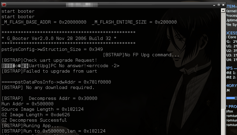
All of these data are the bootloader’s info of the device, loading the kernel/OS in memory, and after a moment, we should be getting an authorization prompt or a shell from which we can execute some commands (stack and heap dump’s, CPU status, upgrading firmware, etc…). In my case, I had a shell right away, not of a big surprise since that such a device is a cheap old one, and I’d guess that the majority of such devices aren’t very well secured or implementing serious security practices.
